- Other Consumer Electronics[10]
- Integrated Circuits[10]
- Paper Crafts[10]
- Other Holiday Supplies[10]
- Gift Sets[7]
- Openers[9]
- Toy Musical Instrument[4]
- Toy Accessories[10]
- Toy Parts[10]
- Contact Person : Ms. Shen Anna
- Company Name : Shenzhen Cheer Trend Development Ltd.
- Tel : 86-755-36616895
- Fax : 86-755-37693912
- Address : Guangdong,Shenzhen,No 8th, Feng men ao section 1, Gangtou village, Bu ji town, Long gang district
- Country/Region : China
- Zip : 518000
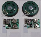
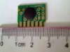
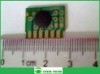
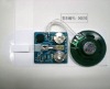
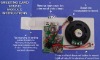
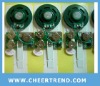
Sound IC chip(Mask /1-CH/CMOS IC)


Related Product Searches:Sound IC chip(Mask /1-CH/CMOS IC),High Quality,Sound IC chip, voice ic chip,AM9AC series
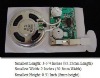
FEATURES(1). Single power supply can operate from 2.0V to 6.4V (in this range, user can set Rosc as a fixed value).(2). The total voice duration is about 3.5, 7, 14 or 21 seconds those can be partitioned up to 8 voice_sections. Each voice_section length is flexible.(3). Voice length can be individually up to 3.5, 7, 14 or 21 seconds at 6kHz S.R. for each voice_section.Voice+mute length can be individually up to 11, 21, 21 or 21 seconds at 6kHz sample rate for each voice_section.(4). Total 16 voice_steps are available for 2 sub_tables. Each sub_table can only use maximum 8 voice_steps. For each voice_step, it can specify one voice_section and IO1 output enable options if IO1 is set as an output.(5). Build in oscillator, 15 kinds of playback speed option for internal resistor used : ( 4.0k ~ 18.1kHz)<Internal oscillator--OSC pad must be bonded to GND>(6). IO1 can be either input or output pin (Mask option). (7). Optional “Two Triggers Input” (TG and IO1), or “One Trigger Input” (TG pin only).(A). Each input pin has mask options for Edge/Level, Hold/Unhold and Retrigger/Irritrigger trigger modes.(B). TG input can choose CDS+1M,CDS,1M pull-low,10M pull low or floating input type.(C). IO1 input can choose CDS+1M,CDS,1M pull-low or floating input type.(D). Debounce time: Long debounce for push buttons. Short debounce for switches. ( In Two Triggers Input Mode, only one kind of debounce time is available.)(E). Priority--TG > IO1.
(8). IO1 has the following output option A~F (A). Stop_High pulse : high active stop pulse output whenever device stop playing.(B). Busy_High active : high active signal output during playing.
(C). Busy_Low active : low active signal output during playing.(D). LED 3Hz flash : 3Hz sink signal output for driving LED during playing at 6kHz sample rate.(E). LED 6Hz flash : 6Hz sink signal output for driving LED during playing at 6kHz sample rate.(F). LED dynamic 2/4 : dynamic sink signal output for driving LED during playing. *Where (D) and (E) is the LED flash rate at 6kHz sample rate. For different sample rate, the LED flash rate is different from original 3Hz or 6Hz.(9). PWM1 and PWM2 can directly drive buzzer or 8, 16, 32 or 64 ohms speaker.(10). The voice_section length of “voice length + mute length” must be the multiple of 80Hex (AM9AC0036) or 100Hex (AM9AC0076, AM9AC0146, AM9AC021D).(11). In voice_section sequence arrangement (00~07), If there are some voice_sections with only mute and without voice, they should be put next to the last voice_section with voice. Besides, that is not allowed to put a pure mute voice_section between 2 voice_sections with voice, or put the pure mute voice_section on first place (00).(12). Oscillator selection(A). External oscillator: Connect OSC pin to Vdd with a resistor, Rosc.(B). Internal oscillator: Connect OSC pin to GND. (Not suggested because of frequency shift and system stability)
Choose Mode
Sound IC chip(Mask /1-CH/CMOS IC)